

Hydraulic Test Equipment > Flushing & Pressure Test Rig > Fixed Flushing & Pressure Testing Rig
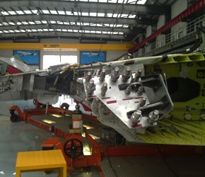
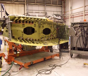
The hydraulic test rig has two purposes. These are to test the integrity
of the installed aircraft hydraulic systems in respect to pressure and
leakage and to cleanse the internals of the system by flushing out any
contaminants. In other words they are combined flushing and pressure
aerospace test rigs.
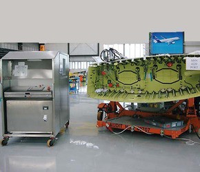
The system is a semi static facility compromising two hydraulic test
rig units statically plumbed into the production area. The test rig
units can be decoupled from the plumbing and removed for major service
or repair if necessary. Consequently they are built within frames that
allow lifting, handling and safe transport. The hydraulic test rigs have
suitable access points for maintenance.
The hydraulic test rig units have reservoirs to store the Skydrol� hydraulic
fluid and pumps to provide pressure. The hydraulic test rig units also
provide pressurised nitrogen into the system. The hydraulic test rig units
have electric control systems for both the hydraulic rig itself and the test
operations on the wing.
The rigs are designed to handle phosphate ester hydraulic fluids such as
Hyjet and Skydrol to Airbus specification NSA307110. It is a requirement to
function test the system and check for cleanliness to a standard of NAS 1638
class 7 or better using a particle analyser.
The hydraulic test rig units are electrically controlled programmes via HMI
with manual control. The input is by a touch screen on the front of the rig
and via a remote HMI.
The hydraulic test rig units have a capacity of 400 litres of Skydrol� LD-4
hydraulic fluid held in reservoirs. The structure is of unpainted stainless
steel with survivability and cleanliness in mind. A tray is located at the
bottom of the rig capable of containing 100% of the Skydrol capacity.
The hydraulic test rig units have Skydrol� resistant cable and cable conduit
with the route of the cables and the looms designed to avoid contamination
from hydraulic leaks. Also the design of rig and pipe runs route and collect
any hydraulic leaks with minimal impact on rig, with suitable drain points.
The hydraulic test rig units were supplied fully assembled and tested, and
complete with all general arrangement drawings, test certificates and manuals.
Suction System:
- Nitrogen low-pressure test to 15 bar +0 bar, -1 bar

- System flushing at a minimum flow rate of 100 LPM
- Fluid pressure test at 15 bar +0 bar, -1 bar
- System evacuation: purge system with nitrogen
Main Systems:
- Nitrogen low-pressure test to 15 bar +0 bar, -1 bar
- System flushing at a minimum rate of 100 LPM
- Fluid pressure test at 65-bar +/- 5 bar
- Wing tooling valves closed.
- Fluid pressure test at 150-bar +/- 10 bar
- Fluid pressure test at 350 bar +70 bar, -0 bar
- System evacuation: purge system with nitrogen at approximately 0.7 to 4 bar.
The hydraulic test rigs incorporate the following primary functions:
- Flushing: 122 LPM at a maximum pump pressure of 30 bar
- Pressure testing: 9 LPM at a maximum pump pressure of 420 bar with a proportional
- relief valve via the PLC and HMI to control the pressure.
- Nitrogen system purge and nitrogen pressure test.
- Fluid testing: Utilising a Parker I count particle analyser.
- Separate offline cooling / filtration system utilising an air blast heat exchanger
- Separate reservoir filling pump system